Epibus - MODBUS/TCP integration for ERPNext
Epibus provides an ERPNext integration with MODBUS/TCP networked programmable logic controllers (PLC).
A Programmable Logic Controller, or PLC, is a hardware device used to control machines and processes. It is a computer that is designed to be used in harsh environments. It is used to control machines and processes in manufacturing, oil and gas, water treatment, and many others.
MODBUS is a communication protocol that is used to communicate with PLCs. It is a master-slave protocol, where the master is the computer that is used to communicate with the PLC, and the slave is the PLC itself.
Note that the MODBUS protocol has been around since 1979 before the words 'master' and 'slave' in the context of machinery were considered offensive. The MODBUS protocol is still used today and is the most common protocol used to communicate with PLCs.
The name 'Epibus' is a portmanteau of 'Epi' (from 'Epinomy') and 'Bus' (from 'MODBUS').
Epibus is based on the excellent PyModbus library, which is a pure Python implementation of the MODBUS protocol.
Usage Overview
Epibus configures three DocTypes: Modbus Connection, Modbus Location, and Modbus Action.
Modbus Connection
A Modbus Connection is a configuration for a MODBUS/TCP connection. It contains the following fields:
- Host: The IP address or hostname of the PLC
- Port: The port number of the PLC (default is 502)
- Device Name: The brand and model name of the device (for reference only)
- Unit: The MODBUS unit ID of the device
- Locations: A list of Modbus Locations that are associated with this connection.
Modbus Location
A Modbus Location is a child DocType of Modbus Connection. It is used to map from the proprietary name of the location to the standard IEC 61131-3 name and the integer MODBUS address. It contains the following fields:
- Device Address: The name of the I/O pin on the PLC. This is specific to the brand and model of the PLC. For reference only.
- PLC Address: The standardized IEC 61131-3 address of the I/O pin on the PLC.
- Modbus Address: The MODBUS address of the I/O pin on the PLC. (See information below)
- Location Type: The type of I/O pin on the PLC. (See information below)
Modbus Action
A Modbus Action provides an interface between ERPNext and the MODBUS/TCP connection. It executes a MODBUS read or write operation on a Modbus Location and can be triggered from any ERPNext DocType that is linked to a Modbus Action. It contains the following fields:
- Modbus Connection: The Modbus Connection that this action will use.
- Modbus Location: The Modbus Location that this action will use.
- Action: The type of action that this action will perform. (See information below)
- Bit Value: The value that will be written to the Modbus Location. (Only used for write actions)
- Warehouse: Warehouse to Watch. Trigger this action when an item is moved from this warehouse.
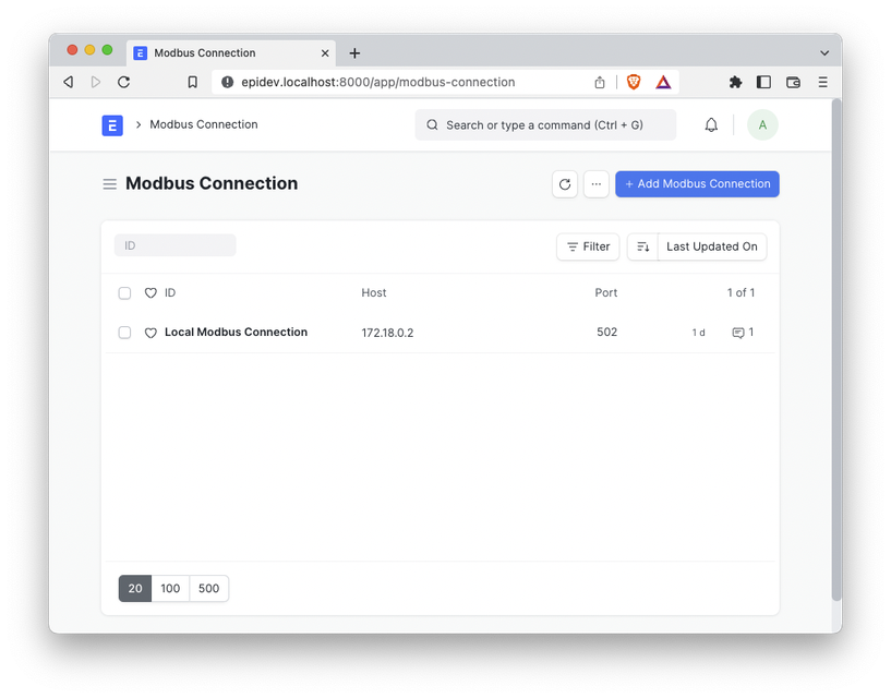
Creating a Modbus Connection
- In the Awesome Bar, search for 'Modbus Connection List' and click on the result.
- Click the + Add Modbus Connection button.
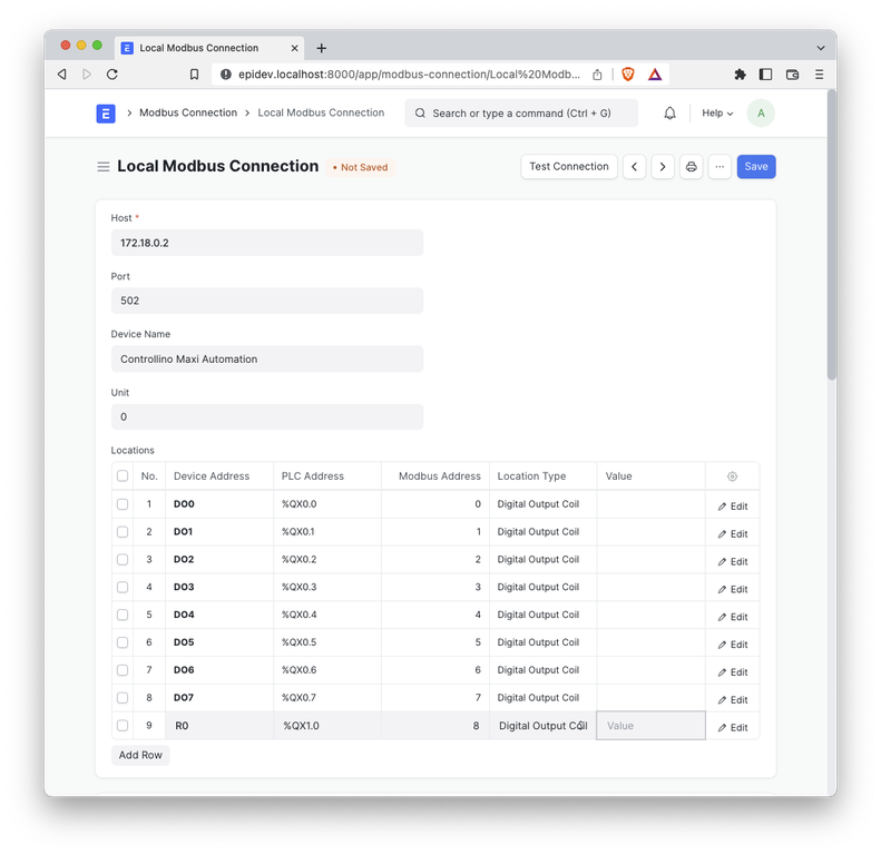
 1. Enter the following information:
- Name: A unique name for this connection. You can connect to any number of PLCs with this app.
- Host: The IP address or hostname of the PLC
- Port: The port number of the PLC
- Device Name: The brand and model name of the device (for reference only)
- Unit: The MODBUS unit ID of the device (defaults to 1)
2. Click the Save button.
1. Enter the following information:
- Name: A unique name for this connection. You can connect to any number of PLCs with this app.
- Host: The IP address or hostname of the PLC
- Port: The port number of the PLC
- Device Name: The brand and model name of the device (for reference only)
- Unit: The MODBUS unit ID of the device (defaults to 1)
2. Click the Save button.
 3. Test the connection by clicking the Test Connection button. If the connection is successful, you will see a message that says 'Connection successful'. If the connection is unsuccessful, you will see a message that says 'Connection failed'.
- Click the Add Row button in the Locations table.
- For each I/O pin on the PLC, enter the following information:
- Device Address: The name of the I/O pin on the PLC. For reference only.
- PLC Address: The standardized IEC 61131-3 address of the I/O pin on the PLC.
- Modbus Address: The MODBUS address of the I/O pin on the PLC. (See information below)
- Location Type: The type of I/O pin on the PLC. (See information below)
- Click the Save button again.
Input, Output, and Memory Addressing
The following is from the PyModbus documentation.
PLC applications interact with the external world through Input and Output modules and/or SCADA communication protocols. When designing your PLC applications, you decide which variables should be attached to I/O and communication modules by labeling the variable with a PLC address.
OpenPLC Runtime uses the IEC 61131-3 nomenclature to address input, output and memory locations. The addressing of I/O locations is done through the use of special character sequences. These sequences are a concatenation of the percent sign “%”, a location prefix, a size prefix and one or more natural numbers separated by blank spaces. The following location prefixes are supported:
- I for input
- O for output
- M for memory
The following size prefixes are supported:
- X for bit (1 bit)
- B for byte (8 bits)
- W for word (16 bits)
- D for double word (32 bits)
- L for long word (64 bits)
For example, if you want to read the state of the first digital input into a BOOL variable, you must declare your variable located at: %IX0.0. If you want to write the contents of a UINT variable into the second analog output, you should declare your UINT variable located at %QW2.
Note: PLC to physical I/O mapping is platform dependent. For more information on PLC I/O mapping for every supported platform, check: 2.4 Physical Addressing
As you probably have noticed, bit (X) PLC addresses have a two-part hierarchical address. The least significant part (right-most) can be interpreted as a position in a byte and must be in the range 0 to 7. The most significant part (left-most) must be no more than 1023. Parts are separated by a single period. Data sizes other than X have a one-part hierarchical address. They must not contain a period (.) and must be no more than the maximum memory location address for your platform.
The following are invalid examples of PLC addresses in OpenPLC for the stated reason:
- %IX0.8 The least significant index is greater than 7.
- %QX0.0.1 Three-part hierarchy is not permitted address.
- %IB1.1 Two-part hierarchy is only allowed for X data size.
Example Pinout Configuration for a Modbus Connection
Below is an example pinout from the Controllino Maxi Automation PLC. It is from the Open PLC Project.
/************************PINOUT CONFIGURATION*************************
Digital In:  AI2, AI3, AI4, AI5, AI6, AI7, AI8, AI9     (%IX0.0 - %IX0.7)
             AI10, AI11, DI0, DI1, DI2, DI3, IN0, IN1   (%IX1.0 - %IX1.7)

Digital Out: DO0, DO1, DO2, DO3, DO4, DO5, DO6, DO7     (%QX0.0 - %QX0.7)
             R0, R1, R2, R3, R4, R5, R6, R7             (%QX1.0 - %QX1.7)
             R8, R9                                     (%QX2.0 - %QX2.1)

Analog In:   AI0, AI1, AI13, AI13                       (%IW0 - %IW3)

Analog Out:  AO0, AO1                                   (%QW0 - %QW1)
*********************************************************************/
License
MIT
Epinomy® is a registered trademark of Applied Relevance, LLC.